Version UPDATE: The Lock-in+PID v0.2.2-1 update now supports the Red Pitaya ecosystem 2.0
Lock-in+PID is an application for the RedPitaya enviroment / STEMlab 125-14 board that implements an Oscilloscope application and a Lock-in amplifier. It’s based on relese-0.95 scope application of the RedPitaya project.
The aim of this application is to provide a toolkit for labs measurements and system control uses. The functionalities are organized in “instruments”.
Publication
A rigorous description of the App design and applications can be find in this article on scientific journal: Compact embedded device for lock-in measurements and experiment active control.
News: There is a new section on this web page about “derivated works”, including applications
for Red Pitaya that are similar in design to Lock-in+PID or that are useful complements:
- Harmonic (only) Lock-in, with some extra features
- Peak simulator App, to simulate the spectral response of a system under scan/locking
- Third-party projects inspired in
Lock-in+PID
PhD Thesis
This work was done in the context of a Physics PhD career in the Universidad de Buenos Aires. The thesis and the defense are published on-line in spanish language and can accessed here:
Features
- Web control interface
- Python based remote control (designed for Spyder under Linux)
- Complete Free Software source code.
- Oscilloscope application
- Lock-in amplifier (only with internal oscillator)
- Modulation generator
- Harmonic functions (from 3 Hz to 50 kHz)
- Two 1f functions in quadrature (sine and cosine)
- One 1f function with phase control
- One 2f function with phase control
- One 3f function with phase control
- Square functions (from 30 mHz to 31 MHz)
- Two 1f functions in quadrature
- One 1f function with phase control
- Harmonic functions (from 3 Hz to 50 kHz)
- Scan control
- Two configurable PID filters
- Proportional, Integral and Derivative controllers
- Set-point control
- Several order of magnitudes
- Lock controller
- System for making closed-loop stabilization schemes
- Graphic tool for lock start-point selection
- Auto-lock / relock system
Where to start
If you want to know more about how to use this app you should read the TheApp > Instruments menu.
Download and install
For the last release, check TheApp/install/. The application comes in three flavors: Default, DEBUG and RELOAD. You’ll be looking probably for the Default option.

The source code is available at GitHub
Source Code
The project code is available on GitHub: github.com/marceluda/rp_lock-in_pid/
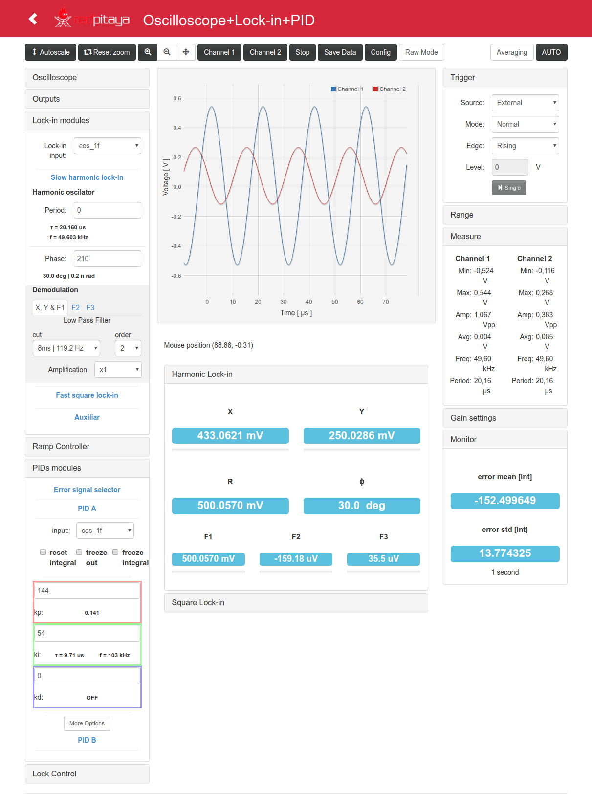
The App Web GUI

Use cases
The application implements a lock-in amplifier and two PID filters. These elements are suitable for several stabilization schemes implementations: they measure low amplitude signals to get a physical system state and then use a closed-loop feedback system to stabilize the state of the physical system to a desired one.
The closed-loop system is an stabilization-scheme, usually descrived in control theory. The actually probed schemes are mostly from laser-optics applications, because Lock-in+PID was created in an optics lab with this purpose. But all off then are ready to use in any physical system o engineering project controlled by electric signals.
Lock-in+PID most common usage
Phase sensitive measurement of small signals
Implementation of the lock-in technique to measure the response of a system under and oscillatory excitation. If you use an excitation signal of frequency f (reference signal), the system response will have also a f Fourier component. With the lock-in technique you can filter the f component and measure its amplitude and phase relation with the reference signal. The filtering process enables you to reduce the noise signal from the other frequencies components and amplify the response one, enhancing the signal-to-noise ratio. We call this process demodulation. Also, you can demodulate the input signal using 2f and 3f frequencies to get harmonic components that have information of non-linear behavior of the physical system.
Closed loop system schemes for variable stabilization
You have a physical variable that you want to stabilize against environment changes.
You can measure it and convert it in an electrical signal you take from RP input 1.
With Lock-in+PID you can stabilize it to a desired offset voltage value using an error
signal ( error = input1 - offset ) that feeds a PID filter. The PID output is a
correction signals that can be added to the control signal that actually
controls the physical system.
This is called a close loop scheme. If it is well designed, you can use it to make the physical system to be “tied” to a particular state.
Combined systems
Some times you can only measure the physical system that you want to stabilize using information get by the lock-in technique. You can combine both techniques to stabilize, for example, the phase of a system, the derivative of the response signal or the noise-filtered amplitude of the response signal, building a lock-in scheme whose output will be used as the error signal for PID input.
Applications tested in lab
- Stabilization of laser wavelength to atomic transition
- Stabilization of laser wavelength to Fabry-Perot interferometer (Pound-Drever-Hall)
- Stabilization of VCO frequency to an electronic reference (Crystal or RCL circuit)
Derivated works
Same versions of the same App witho minor changes where made for specific features and applications. The known works are listed in: TheApp > Derivated works menu.