The Red Pitaya project
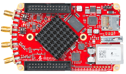
Red Pitaya is a private company that works in instrumentation hardware developing for labs and engineering applications. The main product of this company is the STEMlab-board (originally called Red Pitaya itself). This board is an embebed device that combines a computer with ARM processor, an FPGA and a electronic board with ADCs and DACs designed to replace labs instruments.
The project started with an Open Source philosophy for software and a Closed Source philosophy for the hardware design. Red Pitaya sells you the board an offers you the compiled software, but you can use your own soft, starting from your own or from the Red Pitaya Open Source code on git-hub.

The STEMlab product
The STEMlab was designed to provide multiple functionalities. It can be used to replace (under some conditions) several lab instruments:
- Oscilloscope
- Function generator
- Spectrum analyser
- PIDs filters
The different utilities are packed in “STEMlab Applications”. The device itself runs a GNU/Linux Operative System with a web server that provides access to users from any device with browser support (PC, notebooks, tablets, cell-phones). When you connect to it through a network you access a freamwork where you can use, add or remove that applications. Some Open-Source (and free) applications are available on internet. You can buy others.
Each application has 3 parts:
- An FPGA design: A digital circuit that process on “real time” ( 125 MHz internal clock) and in parallel all the hardware inputs and controls all the hardware outputs.
- A Software logic: A set of routines to process the user actions and make changes on the FPGA registers and switches, and control in this way the hardware behavior. Also, this routines process the data that comes from hardware to send it to the user.
- A Frontend: An interactive web page provided by the web server and run in the user web browser that is the interface to user interaction. This web page shows the data in graphical interface and provides a set of HTML controls that lets the user commands the hardware.
Hardware of STEMlab 125-14 (originally Red Pitaya v1.1)
STEMlab comes in two versions: STEMlab 125-14 and STEMlab 125-10. The main difference is the resolution of the fast input/outputs (14 bits vs 10 bits). The Lock-in+PID App was designed to be used in STEMlab 125-14. Here, some hardware specifications.

Some of the main characteristics of the hardware:
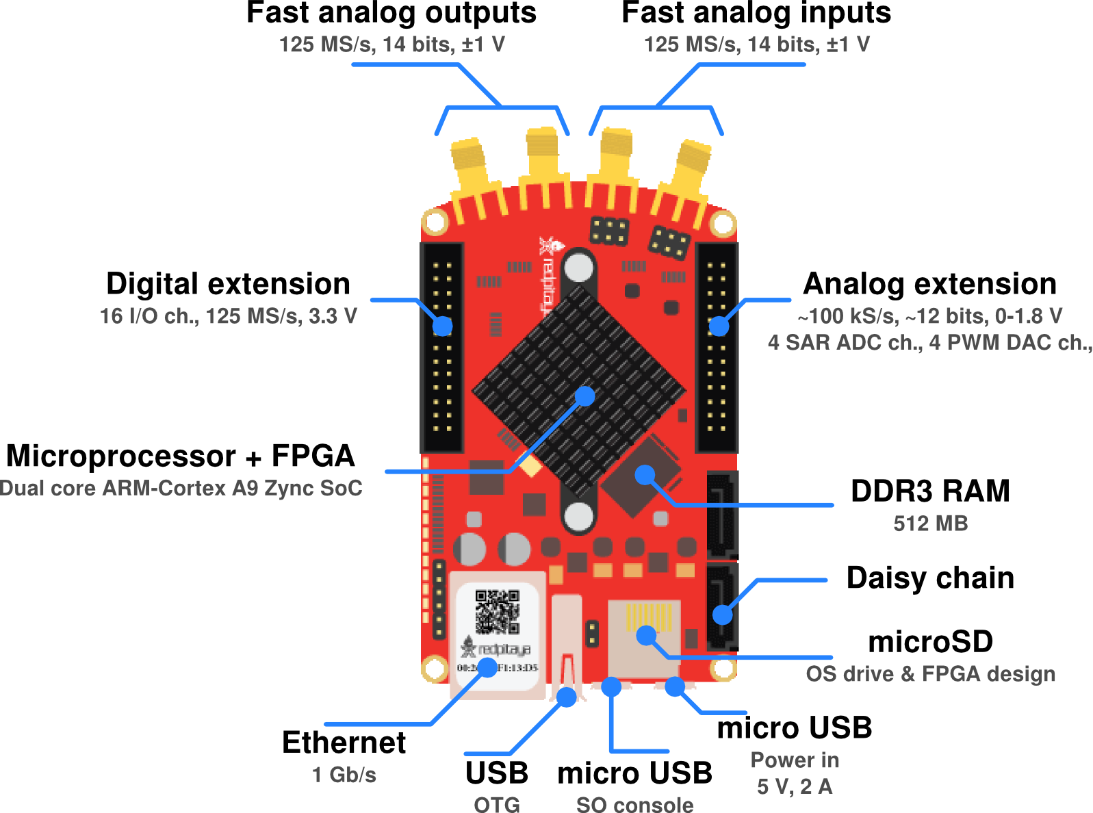
- 2 Fast Analog to Digital Converters (
in1,in2). 125 MSamples/sec, 14 bits resolution, ±1 V (or ±20 V selectable by jumper settings) - 2 Fast Digital to Analog Converters (
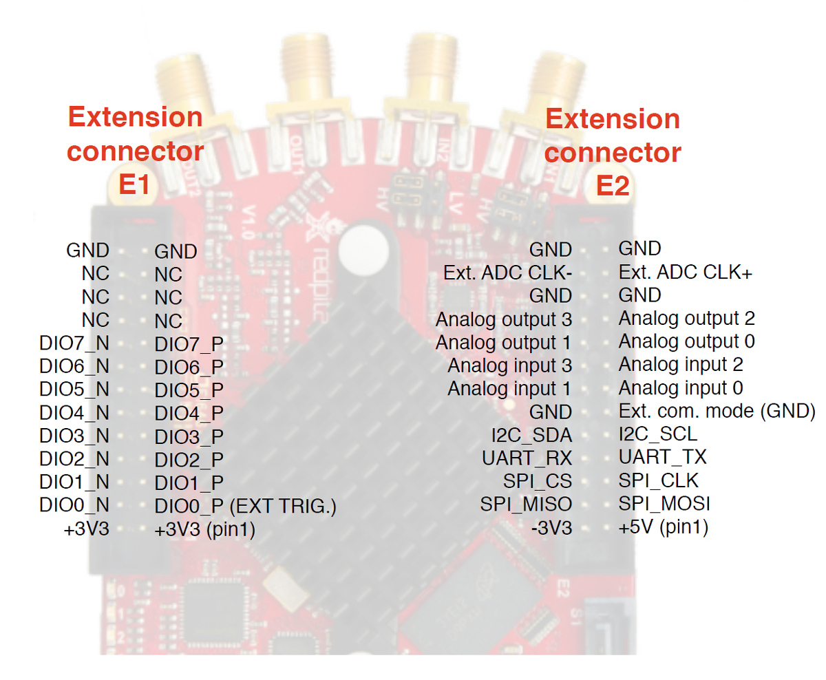
out1,out2). 125 MSamples/sec, 14 bits resolution, ±1 V - Extension connector E1 for digital signals
- 16 input/output 3.3 V digital signals that can be controlled by software or FPGA.
- One of this signas is used in the oscilloscope instrument for output digital trigger.
- GND Ground pins
- 3.3 V pins for shield power supply
- Extension connector E2 for Slow Analog signals and other applications
- 2 pins for external clock supply
- 4 Slow Digital to Analog Converters (
slow_out1,slow_out2,slow_out3,slow_out4). Based in PWM conversion, 100 kSamples/sec, almost 12 bit resolution (0 to 2512 int), 0-1.8 V. - 4 Slow Analog to Digital Converters. 100 kSamples/sec, 12 bit resolution, 0-3.5 V.
- UART interface
- I2C interface
- SPI interface
- 5 V and -3.3 V power supply for shield
- ARM based computer
- Dual Core ARM cortex A9 processor
- DDR3 512 Mb RAM memory
- MicroSD HD (up to 32 GB)
- FPGA Xilinx Zynq 7010 SOC Xilinx Zynq 7010 SOC
- 1 Gbit Ethernet port for wired network
- USB interfase
- micro USB interfase for Operative System serial console
- micro USB interfase for power supply input (5 V, 2 A)
Extension connectors pinout
