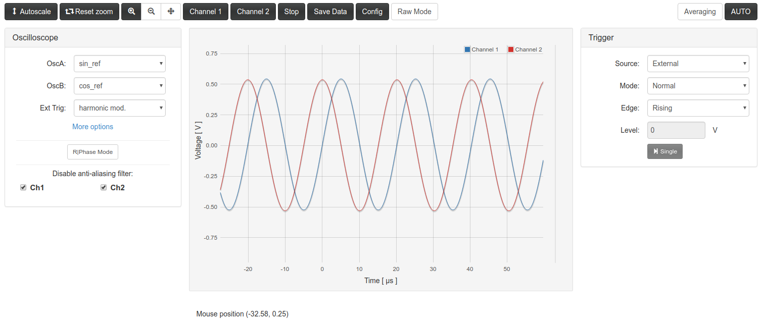
The Oscilloscope instrument lets you see the wave form of two signals of the device. They can be internal signals (produced inside the FPGA module) or external (taken through ADC inputs).

The original application
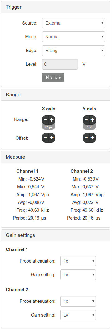
As was said, this instrument is based in the scope application) of the Free Software repository for the Red Pitaya Comunity. All the controls of the original application were kept in the right hand column. In these panels you can control the trigger behavior, the time and amplitude scales, monitor the statistics for each channel, etc. Only the “Monitor” panel is new, used for the PIDs instrument.

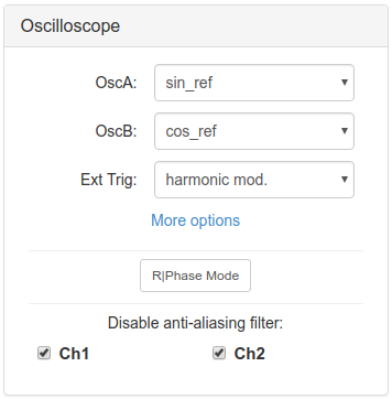
The original application was designed to measure only de ADC inputs. This version was modified to use de oscilloscope functionality on other signals. The controls for this purposes are in the left panel.
Selection of signals
The main new feature of the oscilloscope application is the possibility to choose which signal you want to view. You can do this from the left panel called “Oscilloscope”.

These are the signal available to view:
| Signal name | Comes from | Description |
|---|---|---|
| in1 | ADC inputs | Hardware input 1 |
| in2 | ADC inputs | Hardware input 2 |
| error | PIDs | Error signal |
| ctrl_A | PIDs | PID A output + Ramp A |
| ctrl_B | PIDs | PID B output + Ramp B |
| Ramp A | Ramp | Ramp signal A of Ramp Instrument |
| Ramp B | Ramp | Ramp signal B of Ramp Instrument |
| pidA_in | PIDs | Input signal for PID A |
| pidB_in | PIDs | Input signal for PID A |
| PID A out | PIDs | Output signal from PID A |
| PID B out | PIDs | Output signal from PID A |
| sin_ref | Local Oscillator | Sine signal |
| cos_ref | Local Oscillator | Cosine signal |
| cos_1f | Local Oscillator | Harmonic signal at same frequency that cos_ref and with a phase relation to cos_ref |
| cos_2f | Local Oscillator | Harmonic signal at double frequency than cos_ref and with a phase relation to cos_ref |
| cos_3f | Local Oscillator | Harmonic signal at triple frequency than cos_ref and with a phase relation to cos_ref |
| sq_ref | Local Oscillator | Square signal (positive and negative) |
| sq_quad | Local Oscillator | Square signal in quadrature with respect to sq_ref |
| sq_phas | Local Oscillator | Square signal with a phase relation to sq_ref |
| square ref (bin) | Local Oscillator | Square signal in phase with sq_ref, without negative values |
| signal_i | Lock-in | Lock-in input signal |
| Xo | Lock-in | Demodulated signal using cos_ref as reference |
| Yo | Lock-in | Demodulated signal using sin_ref as reference |
| F1o | Lock-in | Demodulated signal using cos_1f as reference |
| F2o | Lock-in | Demodulated signal using cos_2f as reference |
| F3o | Lock-in | Demodulated signal using cos_3f as reference |
| sqXo | Lock-in | Demodulated signal using sq_ref as reference |
| sqYo | Lock-in | Demodulated signal using sq_quad as reference |
| sqFo | Lock-in | Demodulated signal using sq_phas as reference |
External trigger
The original application lets you use an external signal to trigger the oscilloscope acquisition. Here you can select where this external trigger comes from. The options are specified in this table:
| Trigger option | Source | Description |
|---|---|---|
| None | - | Never triggers |
| Pin | Hardware | The trigger is taken from pin DIO0_P of RedPitaya hardware digital input |
| Ramp floor | Ramp | Triggers when Ramp A signal reaches the minimum value |
| Ramp Ceil | Ramp | Triggers when Ramp A signal reaches the maximum value |
| Harmonic Mod. | Lock-in | Triggers with cos_ref start point |
| Square Mod. | Lock-in | Triggers with sq_ref start point |
| Out of Lock | Auto-lock | Triggers when auto-lock system doesn’t achieve the locked condition |
| Jump Trigger | Auto-lock | Still not implemented |
| Lock control Trigger | Auto-lock | Triggers when auto-lock system finds the “start locking” condition |
Anti-aliasing filter
The oscilloscope FPGA implementation includes anti-aliasing filters that are useful in several situations but may distort the real signal wave form in others situations. The effect over is similar to a low-pass filter applied to both channels. This filters can be disabled for a more precise representation of the measured signal.
R and Phase switch
When this option is switched on, the selected OscA and OscB inputs are pre-processed before been displayed as Channel1 and Channel2 in the plot area:
Channel1  =  sqrt( OscA**2 + OscB**2 ) ;
Channel2  =  atan2(OscB,OscA) ;
In this way, if you choose OscA=Xo , OscB=Yo , the displayed Channel1 and Channel2 in
the plot area are the R and Φ respectively:
Other Features
The top button bar includes some other features to control de visualization

- Autoscale: Scales the vertical axis to use the whole screen on displayed data.
- Reset zoom: Resets the zoom options to default.
- ChannelX buttons: Switch on/off the visualization of Channel X
- Stop: Stops data acquisition .
- Save data: Displays a modal windows with options to exporte the visualized data to Python/Numpy, Matlab/Octave or CSV .
Some technical information
-
The oscilloscope internal memory for each channel is a 16384 length array of 14 bits signet int numbers. For data visualization in the web frontend this array is decimated to a 1024 length and converted to float type. When you save data using the web application you only save this 1024 arrays. For higher precision you would need to acquire the data using scripting tools.
-
The Wep App is constantly asking the web server for curves and parameters update, waiting 50 ms between each query.
-
The parameters of the application are updated to the web frontend if they change in the FPGA through scripting tools. So you can use a mixed control scheme, if you want.
-
Each time the Web App query for new data the FPGA oscilloscope module starts a new triggered acquisition. If you wan to use a mixed scheme and acquire channels with the scripting tools, first you have to stop the web app for a while.
-
For more details, see the development documentation