Both Lock-in amplifiers have their own internal oscillators for reference signals. They can also be used as function generator for any other purpose.
Harmonic functions
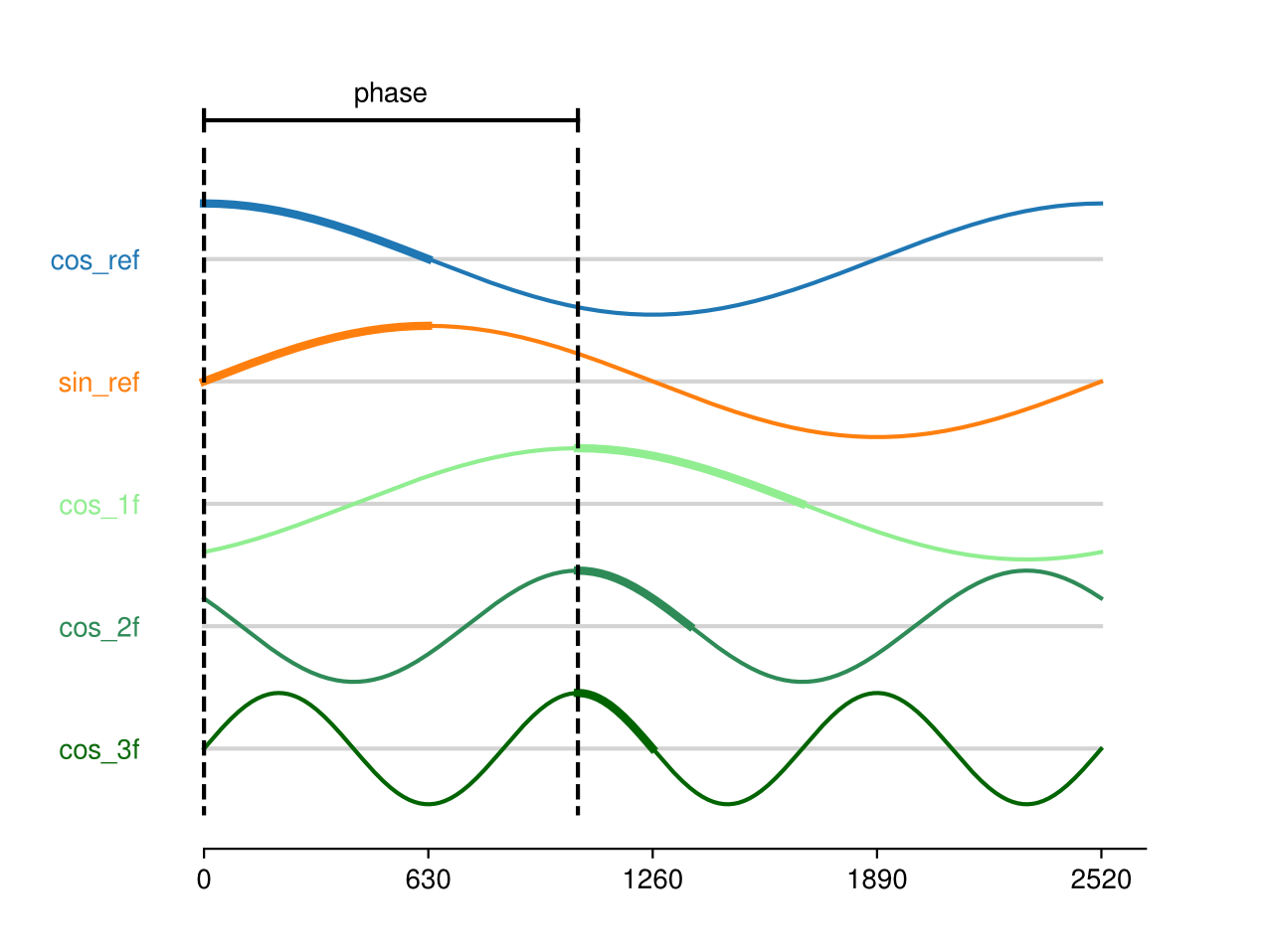
The harmonic functions are built into an array of 2520 points of 14 bits signed int stored in Read Only Memory (ROM) modules in the FPGA layer.

All of them are discretized versions of \(cos(\omega t)\), \(sin(\omega t)\), \(cos(\omega t + \phi)\), \(cos(2 \omega t + \phi)\) and \(cos(3 \omega t + \phi)\). The discretization was carefully made in a way that all the Fourier orthogonality relations between them are kept when \(\phi = 0\).
The phase parameter controls the steps of delay between cos_ref and cos_?f signals and is used to set \(\phi\) value.
The period parameter (hp inside FPGA) is the number of internal FPGA clock periods that last each point
of the array. The min value of hp=0 means each points corresponds to a clock period (8 ns), making the
full Cosinus period of \(\frac{1}{2520 \cdot 8 ns} = 49.6 kHz\). With hp=1, each point last 16 ns, an so on.
In the graphic, the thick part of the plots are the portion of the data points actually saved in ROM, for space economy. The values are repeated with order and sign change to build the signals on the run.
Schematics of FPGA layer
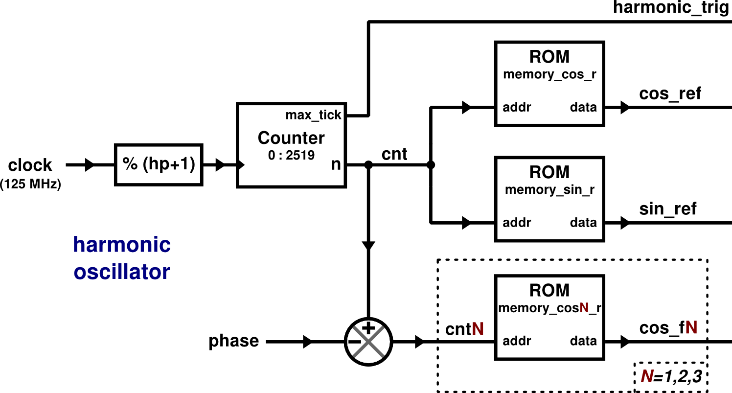
The following graphic represents the FPGA logic circuit for the harmonic functions generation. It’s not rigorous, for simplicity. Lets you understand the way the parameters affects the generated functions.

Each function is stored in a ROM module. The ROM outputs the value stored in the position
set by the addr input.
The addr input of the ROM modules for cos_ref and sin_ref is labeled cnt an is fed by a counter that
goes from 0 to 2519 and start again. The counter changes is value at the time rate set by the frequency
divider thats lowers down the frequency of the FPGA internal clock (125 MHz). The lower value mean no division
at all.
The memory modules address for cos_f? functions are fed by the same cnt number minus phase, so they are
phase shifted respect to cos_ref and sin_ref. The phase parameter of the Web App control this.
Square functions
The square functions are build on the run. They work as frequency dividers applied to the internal FPGA clock ( frequency: 125 MHz , period: 8 ns).

There are three binary signals (sq_ref_b, sq_quad_b and sq_phas_b) controlled by two parameters
(unsigned int sqp and phase_sq). If sqp==0, the binary signal is taken from
the sign bit of an harmonic signal (sq_ref_b from cos_ref, sq_quad_b from sin_ref). In that case, square and harmonic oscillators are synchronized.
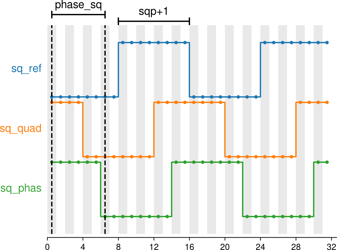
When sqp>0, the period of square signals is: \(({\color{var}\texttt{sqp}}+1) \cdot 2 \cdot 8 ns\).
So, sqp+1 is the number of clock ticks of half period.
The sq_quad_b signal is in quadrature respect to sq_ref_b and is delayed by a quarter period:
(sqp+1)/2 clock ticks. The division has not decimal digits, so the real quadrature is achieved only on
odd values of sqp. The difference is only relevant on high accuracy lock-in measurements or in high frequency uses (when the relative difference in period is higher).
The sq_phas_b signal delayed by phase_sq clock ticks respect to sq_ref_b and is useful for
arbitrary phase setup.
Three 14 bits signed signals are built from binary signals: sq_ref, sq_quad and sq_phas respectively. These are actually used for demodulation and for output. Each 0 is mapped to
-4096 and each 1 to 4096, which means an output value of ±0.5 V.
Schematics of FPGA layer
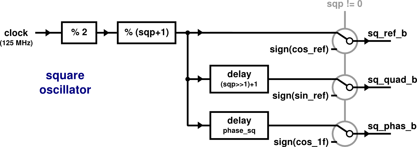
The following graphic represents the FPGA logic circuit for the square functions generation. Again, it’s not rigorous, for simplicity.

The three signals are built from clock signals using some frequency dividers and delay modules.
The clock signal (square signal of 125 MHz frequency / 8 ns period) is lowered down by two
frequency dividers: divided by 2 and by \(({\color{var}\texttt{sqp}}+1)\).
The higher frequency is achieved at sqp=1:
\(31.25 \; \text{MHz} \;=\; \frac{125 \; \text{MHz}}{ 4 }\) .
sq_ref_b refers to reference signal. The signal sq_quad_b is delayed
to be in quadrature respect to sq_ref_b. The delay is
\((\frac{\color{var}\texttt{sqp}}{2}+1)\) clock ticks length (the division is done by the
shift operatorsqp>>1, whose result has not decimal digits and rounds all to
the lower integer value).
The sq_phas_b signal is delayed by phase_sq clock ticks length.
Web Frontend

In the Lock-in panel, both oscillators can be configured.
Under the Slow harmonic lock-in section you can set the fpga hp parameter using the
Period control, and the fpga phase parameter using the Phase control.
Under the Fast square lock-in section you can set the fpga sqp parameter using the
Period control, and the fpga phase_sq parameter using the Phase control.
All the controls are configured using unsigned int values and a human-readable value is shown below to make it easier to understand.