The Ramp generator instrument is used to make configurable triangle functions for scanning purposes.
The FPGA module generates two signals: ramp_A and ramp_B.
ramp_B is a copy of ramp_A with an scale factor.
Ramp module operation
There are four parameters to control the ramp signals shapes:
ramp_step, ramp_low_lim, ramp_hig_lim and ramp_B_factor.
Another 3 parameters are used to control de behavior:
ramp_direction, ramp_reset and ramp_enable.

| Parameter | Range of values | Web GUI control | Description |
|---|---|---|---|
ramp_step |
[0:4294967295] |
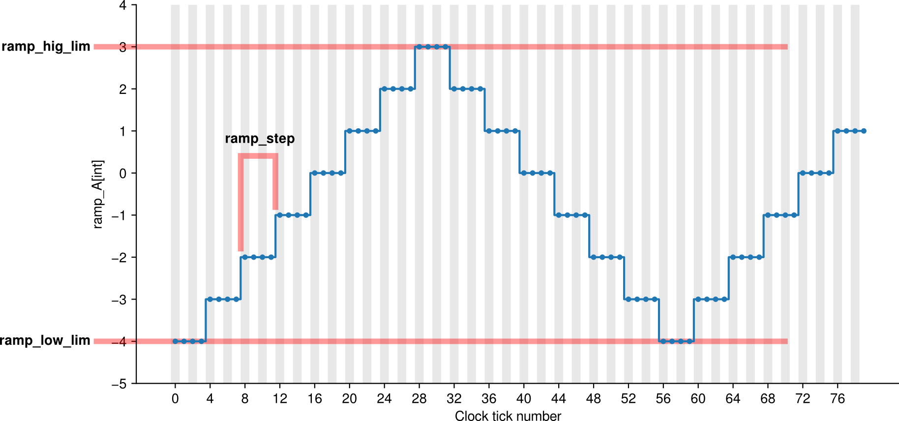
Ramp Step | The module waits (ramp_step+1) clock ticks ( (ramp_step+1) ⋅ 8 ns ) in ecah value, before jumping to the next one. |
ramp_hig_lim |
[-8192:8191] |
Ramp high limit | The highest value that ramp_A signal can have. When ramp_A is going upward and reachs ramp_hig_lim it starts going downward. |
ramp_low_lim |
[-8192:8191] |
Ramp low limit | The lowest value that ramp_A signal can have. When ramp_A is going downward and reachs ramp_low_lim it starts going upward. |
ramp_B_factor |
[-4096:4096] |
Ramp B factor | ramp_B value is defined by ramp_A and this parameter: ramp_B = ramp_A ⋅ ramp_B_factor / 4096 . |
ramp_enable |
[0:1] |
Ramp enable | If set to True (1), the ramp signals advance. If set to False (0), stop. |
ramp_reset |
[0:1] |
Ramp reset | If set to True (1), both signals are set to zero |
ramp_direction |
[0:1] |
Ramp direction | This defines the starting direction (True : upward ) |
To modulo logic is the next one. When ramp_enable is turned on to True it waits (ramp_step+1) clock ticks and then adds 1 to the value of ramp_A, and repeats. When ramp_A reach
ramp_hig_lim instead of adding 1 it start to subtracting 1. When ramp_A reach ramp_low_lim switches again and start to add 1, and so on. When the ramp_direction changes its value
the direction of ramp_A is changed immediately. If you turn on ramp_reset then ramp_A is set to 0. If ramp_enable is turned off (set to False) ramp_A is frozen in its last value.
All the time, ramp_B is calculated from ramp_A using : ramp_B = (ramp_A * ramp_B_factor) >> 12 , which means:
\({\color{var}\texttt{ramp_B}} = \frac{ {\color{var}\texttt{ramp_A}} \cdot {\color{var}\texttt{ramp_B_factor}} }{4096}\).
The chosen parameters to control the module could seem to be “unnatural” for some common applications, but are useful to have low level control of FPGA behavior.
The ramp_step parameter can be seen as a “period control” if you don’t change the ramp limits, but in general case is a “slope control”. This has some advantages when you extend the
total ramp long, because you often have inputs whose curve shapes depends on the ramp slope. For example, if you are scanning a system-under-test and watching the response, and the measure
device has some low-pass-filter effect, changing the slope of the ramp will change the shape of the response curve. So you will prefer to extend the ramp longitude keeping slope constant
rather than keeping the frequency / period.
Web frontend

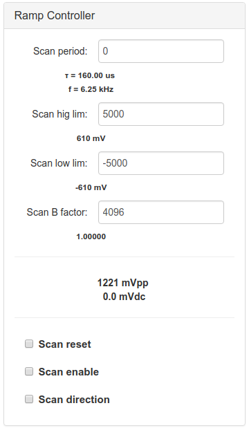
Each FPGA parameter is controlled directly from the Web Interfase. All the input controls use int units and show below the equivalence in Volts following the scale: \(1 \;\text{V}\; = \; 8192 \;\text{int}\).
After the number inputs there is a display that shows the peak-to-peak voltage of the resulting triangle function and the mean value. This can be useful when you want to now the complete ramp amplitude and the center of the ramp.