The lock-in module is composed of two lock-in amplifiers for different scopes:
-
A “standard” harmonic lock-in that uses harmonic signals to demodulate the input signal. This one is less affected by higher harmonics distortion but is more limited in the working frequency range.
-
An square lock-in that uses square signals to demodulate the input signal. Square demodulation has some distortion from odd higher harmonics but is less limited in the working frequency range.
Both uses a local oscillator as reference signal. We will call these the “modulation signals” Here we cover the lock-in demodulation options. The generation of modulation signals is covered in next instrument page.
Lock-in demodulation scheme
The Lock-in amplifier implements a phase sensitive measurement that filters the harmonics components of the input signals, removing undesired frequency components that are not part of the phenomena you want to study.
The most common operation way of a lock-in amplifier is to use a modulation signal (in this case, the local oscillator) to produce a controlled oscillation on one or several parameters of an experimental system under analysis. The system response will have, as well, a modulated component at the same frequency as the used oscillator. The system response plus environment noise will be the input signal \(s(t)\) of the lock-in amplifier.
The filtering is made by multiplying the input signal by a reference signal
FPGA Lock-in implementation
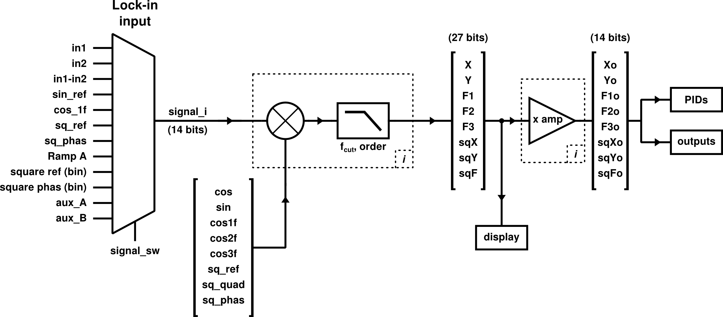
This is an scheme of the lock-in implementation in this application:

The parts inside dotted boxes are repeated 8 times, one per reference signal. The non repeated names
are written between braces and the order keeps the correspondence to reference signals. For example,
the input signal signal_i demodulated using the cos_ref signal is labeled X and, after
amplification, is labeled Xo.

The implementation is not exactly the same for square and harmonic reference, but the way of use is the same, so the demodulation paths are represented all together for simplicity.
There’s a demodulation path for each reference signal, all working in parallel all the time, with a common input signal of 14 bits of resolution. In all the cases, the input signal is multiplied by the reference and this product is filtered by a low-pass filter with configurable frequency cut and order. The result of this is a 27 bits signal suitable for high resolution measurement of quantities. You can access the values of this signals with the Lock-in display (see below). When you need to use de demodulated signals to feed outputs or PIDs filters (all of them with 14 bits resolution) the demodulated signals are amplified and cut. The amplification factor is configurable.
The parameters configuration for any of the demodulation path of both lock-in amplifiers can be set through the lock-in panel of the Web Application.
Harmonic Lock-in
The harmonic lock-in has 5 demodulation paths, for 5 reference signals:
| Signal | Description | demodulated signal |
|---|---|---|
cos_ref |
Base harmonic signal | X |
sin_ref |
Harmonic signal in quadrature with cos_ref |
Y |
cos_1f |
A copy of cos_ref delayed in phase steps |
F1 |
cos_2f |
A copy of cos_ref with double frequency and delayed in phase steps |
F2 |
cos_3f |
A copy of cos_ref with triple frequency and delayed in phase steps |
F3 |
This scheme is versatile because lets you measure both components (X and Y) at the same time, or
use a user defined phase relation on F1. Also, you can get information about the first two harmonics through
F2 and F3. For more details about phase parameter, see Local oscillators help page.
In this lock-in frequencies are restricted to a more limited range than the square one: 3 Hz to 49 kHz
The parameters for X, Y and F1 low pass filter frequency cut, order and amplification are the same.
For F2 and F3, the configuration is separated, because they run on different frequencies.
Square Lock-in
The square lock-in has 3 demodulation paths, for 3 reference signals:
| Signal | Description | demodulated signal |
|---|---|---|
sq_ref |
Base square signal | sqX |
sq_quad |
Square signal in quadrature with sq_ref |
sqY |
sq_phas |
A copy of sq_ref delayed in phase_sq clock periods (8 ns) |
sqF |
In this lock-in frequencies can go from 30 mHz to 31 MHz. The last value correspond to the hardware limit of lock-in realization, using reference signals defined with 4 point (32 ns period = 4 * 8 ns of RedPitaya FPGA clock).
Lock-in amplifier / Phase sensitive detection theory
Some external links introducing to Phase sensitive detection and Lock-in amplifier instruments.
- Phase sensitive detection as a means to recover signals buried in noise
- Principles of lock-in detection and the state of the art - Zurich Instruments White Paper
- About Lock-In Amplifiers - Application Note #3 of Stanford Research Systems
- Lock-in Amplifier Tutorial - Bentham