This instrument is a compilation of tools useful to set up a feedback stabilization scheme. The tools were through to ease the procedure of looking for a desired stabilization condition, starting automatically the the stabilization system and detecting when the stabilization procedure fails to take actions.
System variable stabilization
For the sake of clarity, we describe in the next items the idea behind the stabilization application. For detailed analysis refer to Control Theory text books.


- You have a system property or variable you want to control or stabilize to a fixed value.
- You can measure this variable or some value associated to this variable that we will call the system output.
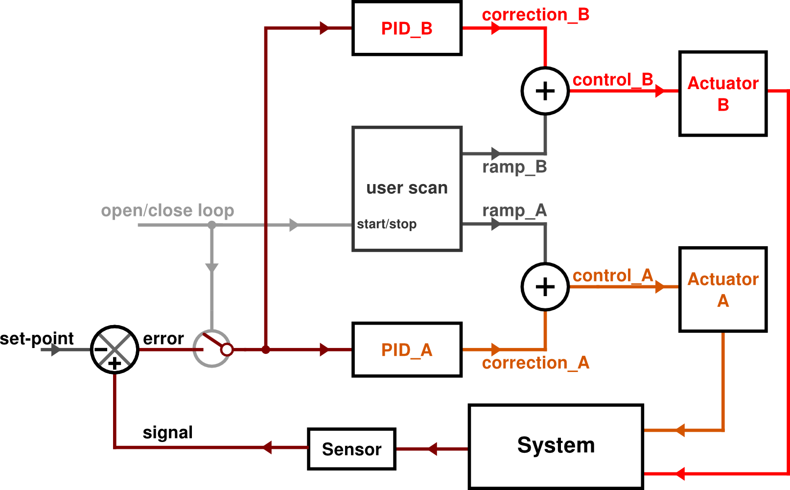
- You can control the system in some degree using a control signal (in this application you can use up to two control signals, see “Example with two actuators”) that changes the state of the system in a way that generates a system response.
- You cannot control all the system variables. The uncontrolled variables (i.e.: environment, random variables, noise, etc) makes undesired changes on the value of the variable you want to control and this changes can be measured on the system response.
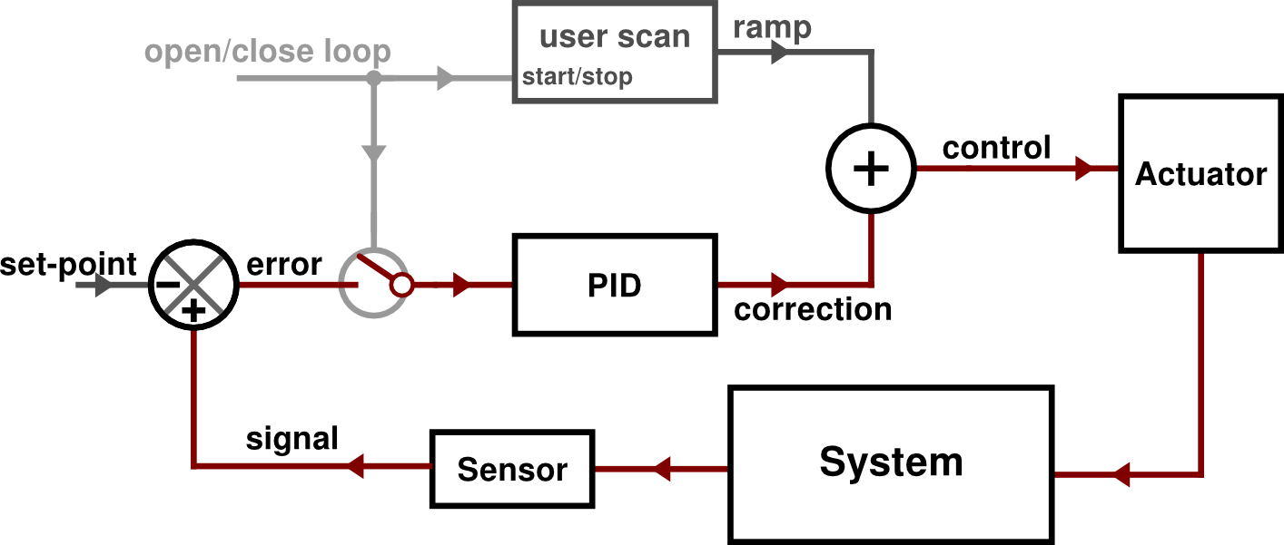
- So, to control or fix the desired variable (or the system output) you build the following stabilization scheme:
- You measure the system output with a sensor an process it to make a measurement signal (the sensor should be considered in a generalized form: it’s not only the conversion of the physical magnitude to a digital signal, but also the process and conditioning needed; for example, it includes the lock-in demodulation, if you are using it).
- You compare the measured signal with a desired value, called set-point and build an error signal: \(\texttt{error} = \texttt{signal} \; - \; \texttt{set-point}\)
- You process the error signal with a filter (PID). If the error signal is 0, the system variable is in the desired state. If not, you have to modify the system. The filter that process the error signals outputs a correction signal.
- The correction signal is added to the actual value of the control signal used to change the system state.
- A well designed filter will output a correction signal that will compensate the uncontrolled variables changes, making the originally uncontrollable variable a stable well controlled variable.
When you apply the correction signal to control the system and compensate the undesired changes you are working in a closed-loop feedback scheme.
When you are studying the system you want to control, you are operating in a open-loop feedback scheme. For example, if you are measuring the system response and the error signal while you scan the control signal with a predefined function like a ramp.
The aim of this instrument is to provide tools to identify the conditions suitable to pass from the open-loop feedback scheme to the closed-loop feedback scheme in order to make a good stabilization of a desired variable.
The Lock Control procedure
- Setup the hardware inputs of the Red Pitaya to measure the system response.
- Setup the hardware outputs of the Red Pitaya to use control signal
ctrl_Aandctrl_B. - Choose an
errorsignal from the PIDs panel. It can be any input or a demodulated signal from lock-in. - Switch off the “PID A Enable” and “PID B Enable” buttons from the Lock Control Panel.
- Configure and start a Ramp scan using the Ramp Panel.
- Here you can see the system response using one oscilloscope channel, and you can use the other channel to see the Ramp position.
- To ease the next steps it is useful to set up the oscilloscope trigger in external source with Normal mode, and choose from the “Ext Trig” menu the “Ramp floor” option. With this the oscilloscope trigger will be raised when the Ramp_A reaches the bottom value.
- If you need it, set the error offset in the PID panel to choose the position where error signal crosses zero (que locking position).
- Configure the PIDs filters
- Keeping the external trigger configuration, you can use an oscilloscope channel to
see the
pidX_outsignal and the other one to see theerrorsignal. - As long “PID X Enable” switchs are kept off, you can see the
pidX_outsignal in the oscilloscope but it is not added nor affect thectrl_Xsignal you use for output.
- Keeping the external trigger configuration, you can use an oscilloscope channel to
see the
- Now you are ready to lock. With the standard configuration, hitting the “Lock Now” button in the Lock Control panel will automatically stop the Ramp (freezing the output value) and enable both PIDs. Also, you can configure a Auto-Lock start using the tools of this panel.
The Lock Control panel

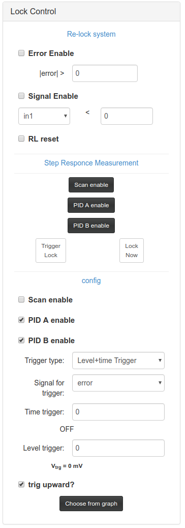
The Lock Control panel has three components:
- The main control, that is always visible, and lets you enable or disable PIDs and Ramp instruments. This section is used to control when to start the stabilization (pass from open-loop to closed-loop feedback).
- Re-lock system, that is hidden by default, and is used to detect if the system is out of lock and start a re-locking procedure.
- Step response measurement: Not working right now.
Main control
The main control has three switch-buttons that enable/disable and show the state of the Ramp and PIDs. Black color means “enabled” (switched on) and white color means “disabled” (switched off).
| Button | Parameter | Description |
|---|---|---|
| Ramp enable | lock_ctrl_aux_ramp_enable_ctrl |
When is on, the Ramp instrument works as expected. When is off, the Ramp instruments stops and the last output value is freezed |
| PID A enable | lock_ctrl_aux_pidA_enable_ctrl |
When is on, the pidA_out signal is added to the ramp_A signal to make the ctrl_A signal. When is off, ctrl_A = ramp_A and the integrator memory of PID A is reset to zero. While the button is off you can still see the pidA_out signal in the oscilloscope (for example, to test the PID behaviour) but without the effect of the integrator. |
| PID B enable | lock_ctrl_aux_pidB_enable_ctrl |
When is on, the pidB_out signal is added to the ramp_B signal to make the ctrl_B signal. When is off, ctrl_B = ramp_B and the integrator memory of PID B is reset to zero. While the button is off you can still see the pidB_out signal in the oscilloscope (for example, to test the PID behaviour) but without the effect of the integrator. |
In the measurement / testing operation, Ramp scan is enabled and the PIDs are disabled (open-loop, without feedback). The stabilization can be started by changing this values to Ramp scan disables and PIDs enabled (closed-loop feedback). We can make this change simultaneously on the three parameters by using the Lock Now button, changing the three values in the same FPGA clock tick (8 ns accuracy). When you clic the Lock Now button the parameters are configured using the values of the checkboxes in the “config” section, whose default values are: Ramp disable, PID A enable, PID B enable. This values can be changed, for example, if you want only one PID on in the final state or if you don’t want to stop the Ramp.
Another way to start the stabilization is by configuring a triggered auto-start. You can configure the trigger type and then clic the Lock on trigger button. When the system reaches the configured condition the state of the enable-controls are switched to the desired one. These are the trigger options:
-
Time trigger: The change is made after some time has passed from the Ramp floor trigger. The time interval is taken from the “Time Trigger” control, under the config section, and is expressed in clock tick units ( 8 ns each unit).
This option is useful when you want to start the stabilization on a desired position of a ramp scan. Theres a control to ease the configuration process that lets you choose from the oscilloscope screen the starting position:
- Use external trigger on Oscilloscope, with Normal Mode.
- Use Ramp Floor as oscilloscope-trigger signal.
- Choose the channels that lets you identify the desired position (i.e.:
errorsignal andramp_A) - Select the “Time trigger” option in the Trigger type combo box of Lock Control panel.
- Click on Choose from graph button.
- Click on the oscilloscope screen position you want to start the lock (note: must be a positive time position less than a period).
- The time position of the point you clicked is configured in the Time Trigger control.
Then you just need to click on Lock on trigger button and the stabilization will start at the chosen time.
- Level Trigger: PENDING
- Level+Time Trigger: PENDING